How about shape factors for bearing capacity? Is it considered in the modified method? Is your model and software limited to cohesive subgrades, or could cover granular subgrade too?
The shape factor for the rectangular load under the tracks are used as defined in BR470:
sc = 1 + 0.2 (W/L) Sg = 1 – 0.3 (W/L) Sp = 1 + (W/L)
Where: W = width of track and L = length of track
Could you please share the formulations used to calculate bearing capacity in your model specifically how the different components (e.g. from platform, geogrid, subgrade) are combined?
The improvement in bearing capacity for the reinforced WP is taken from the empirical work NAUE did in the large-scale laboratory tests. Mainly the triaxial tests helped us to derive an improved punching shearing resistance coefficient “KP . tan δ ” for the WP material in combination with different types of geogrids used in the tests.
What are the limitations of your model? e.g. apply to any subgrade, apply to any shear strength of subgrade etc? What about non-uniform load (e.g. triangular)?
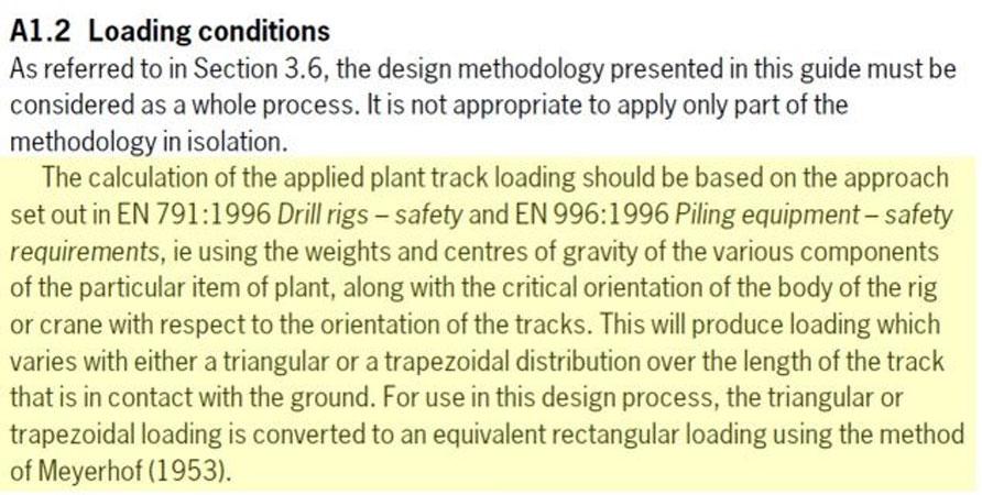
Yes agreed! The model is to be applied to cohesive subgrade conditions only. The undrained shear strength limits in the software for the subgrade are cu = 15-80 kPa (BRE = 20-80 kPa). Regarding the loading scenario we strictly follow recommendations given in BR470 (see quote from BR470 highlighted in yellow).

Surely for an undrained analysis Poisson’s ratio should be 0.5?
Yes 0.5 is acceptable
Does you software/model just works for the tracked mounted plant or can be used for the wheeled ones (or cranes on the outriggers) too?
As our software refers to BR40: “Working Platforms for tracked plant.
If the subgrade is a normally consolidated clay with say OCR of 1.00, do you still use Es in your modelling? If so, how the plastic behaviour is captured?
Only the immediate elastic settlement is considered. No long-term settlements, as a result of consolidation are considered as it assesses the temporary use of the working platform.
Do you adopt the tensile strength of the geogrid at 5% strain in your design?
The tensile strength and stiffness of the geogrid contributing to the improvement in bearing capacity and reduction in settlement is incorporated into the hybrid design model through empirical results from the large-scale model tests that were shown in the presentation. As the deformation/strain in the WP and finally in the geogrid is quite low, the high stiffness at very low strain limits (around 1% strain max) plays an important role in the final performance of the geogrid improved aggregate layer.
If the selected geogrid is not a biaxial one, then the orientation of the track is important, how you capture this?
The geogrid layout should always be biaxial. There are uniaxial geogrids available (if higher strength, high modulus is required) from the geogrid selection menu. If you choose those, always a second layer should be placed perpendicular to the first uniaxial geogrid, so that you get a biaxial system in the end.
So we can add 3th and 4th layer, but can we change the type and strength of the 1st and 2nd layer (predefined layers for analysis)?
Yes, you can delete the types of geogrid from the original suggestion and select the layers yourself in a separate step. It is generally easier and economical to use higher (60kN/m or 80kN/m Secugrid rather than multiple grades of lower strength Secugrid)
How the vertical spacing between two geogrids is decided? As the vertical spacing between geogrid layers in multiple reinforcement case has a great impact on ultimate failure? Does the software suggest min and max spacing for a particular case?
15 – 20cm (after compaction) spacing between individual geogrid layers is recommended. Maximum spacing depends on the type of fill to be used in the WP. For a good quality granular fill, the spacing between layers should not exceed 400-500mm.
Does the hybrid model undertake the FoS check of 1.05 and 1.25 requirements where the reinforcement is ignored?
Yes, it does. The complete design procedure as recommended by BRE470 is checked by NAUE Platform software.
It appears the software is applicable for cohesive subgrade. What about the granular subgrade aspect?
The current version only covers cohesive subgrade conditions. We are working on a second module of the software which covers “granular” subgrade conditions as well.
How about for sub-grade with Cu <20kPa (Limit of BRE method)?
The lower limit of the software is 15 kPa. So, 5 kPa below the lower limit of BR470.
Is your software free to be used?
Yes! Please register online www.naue.com
What are the future research directions within the company?
Developing design software for other geosynthetic applications, like e.g., paved roads, etc.
Does the design software have a lower limit on the vertical spacing between geogrids? i.e. for a given platform thickness, is there a maximum number of geogrids that can be adopted in the profile?
Yes, 15 – 20cm (after compaction) between individual geogrid layers. The maximum number of geogrids is a function of that and the calculated thickness of the WP.
The distance, r, to edge of platform – is that setback distance from edge of track to the platform crest or platform toe? (I believe the sketch in the software showed the distance measured to the platform toe, however I couldn’t see a platform batter slope angle being able to be specified)
The batter is considered conservatively with 1.5(H) : 1(V). As the thickness of the platform is typically rather low (< 1m), a 1:1 batter should be realistic in most of the cases.
For more information please contact our Tech Team on techteam@globalsyntheticsgroup.com.au

